Installation Instructions
NEON SHIFT ROD LINKAGENEON SHIFT ROD LINKAGE
for Harley Davidson only
MCSH
Installation Instructions
CONTENTS
1 – Neon shift rod linkage
1 – Neon transformer
1 – Switch with wire harness
All necessary mounting hardware and
installation instruction
2 Year Limited Warranty
StreetGlow products are warranted against defects in the
material and /or workmanship according to the following
conditions and limitations:
1. Broken Glass, Labor and transportation are not covered
regardless.
2. Warranty is valid for 2 years from date of purchase.
3. Proof of purchase is required to validate warranty.
4. All warranty claims are to be handled by selling agents.
5. Accident, abuse, neglect, improper installation, not
used for its intended purpose are not covered. This
warranty is limited to replacing the defective part
without charge. The company in no event shall be held
responsible for any consequential or special damages.
This warranty gives you specic legal rights and you
may also have rights which vary from state to state.
WARNING!
The retailer shall not be held responsible for any damages
that occur as a result of defective products. StreetGlow
products are recommended for show and o-road use
only. Laws concerning the use of aftermarket lighting
products may vary from state to state. For more
information, check with your local authority.
NEON SHIFT ROD LINKAGE
for Harley Davidson only
MCSH
MOUNTING INSTALLATION (SHIFT ROD LINKAGE)
1. IMPORTANT!! Threaded on each end of the original shift rod are
hime joints. These joints are the means to connect the shift rod
linkage to the shift lever arm on one side and the transmission
arm on the other.
2. Measure the length of the original shift rod linkage from the
center point of the hole in each of the hime joints before
removing the original shift rod. Taking an accurate measurement
is a critical step to ensure proper gear shifting operation once the
original shift rod linkage is replaced with the neon version.
3. Remove the original shift rod and hime joints as a complete
assembly.
4. Remove the hime joints from original shift rod and re-install onto
the neon shift rod.
5. Adjust the length of the neon shift rod to identical length of
original shift rod (from measurements taken in Step 1) by making
adjustments to the nuts on the hime joints.
NOTE: Should there be a need to increase the length shift rod
linkage, 1” or 3“ stainless steel extensions (MCSSE1 / 3) are
available (sold separately).
6. Reinstall the neon shift rod assembly between the shift lever arm
and transmission arm. Tighten hime joint nuts to secure the
neon shift rod to the motorcycle.
7. Test for proper gear shift operation. If the motorcycle does not
shift properly, repeat steps 5 and 6.
NOTE: Be sure that the wiring from the neon shift rod linkage faces
the rear the motorcycle
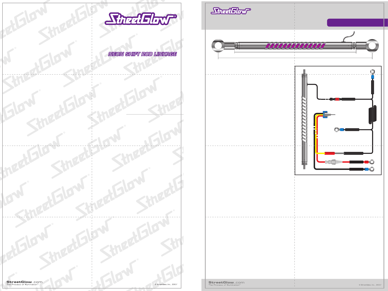
WIRING CONNECTIONS
NOTE: When routing the wires, keep them away from all moving parts and areas of extreme heat (particularly exhaust system components).
1. Choose a location to mount the Neon Transformer. This location must be accessible to both the On/Off Switch with Wire Harness and to
the wire lead from the rear of the shift rod. A good location is under the seat. Attach with double sided tape or the plastic ties provided.
2. Choose a location to mount the On/Off Switch. This location must be accessible to both the battery and to the Neon Transformer. Drill a
¼ ” hole to mount the On/Off Switch.
3. Connect the RED wire with the fuse from the On/Off Switch to the (+) 12V positive side of the battery using ring terminal and cover with
smaller diameter heat shrink tubing. The ring terminal and the smaller diameter tubing are provided. Apply heat using a hair dryer or
heat gun to shrink.
4. Connect the BLACK wire from the On/Off Switch (-) ground to the negative side of the battery using ring terminal and cover with smaller
diameter heat shrink tubing. The ring terminal and the smaller diameter tubing are provided. Apply heat using a hair dryer or heat gun
to shrink.
5. Connect the YELLOW wire from the On/Off Switch to the BLACK WITH WHITE STRIPE wire from the Neon Transformer using butt
connector and then cover with smaller diameter heat shrink tubing. The butt connector and the smaller diameter tubing are provided.
Apply heat using a hair dryer or heat gun to shrink.
6. Connect the BLACK wire from the Neon Transformer to a (-) ground bolt in the motorcycle frame.
7. Connect one of the two solid BLACK high voltage wires from the Neon Transformer to one of the two wires from the shift rod linkage
using butt connectors. Repeat this procedure for the remaining two wires and cover both connections with smaller diameter heat shrink
tubing. Apply heat using a hair dryer or heat gun to shrink.
8. Be sure that all of the wires described in Steps 3, 4, 5 and 6 are completely covered with the smaller diameter heat shrink tubing sleeves
before crimping butt connectors.
9. Individually wrap each of the two butt connectors with larger diameter heat shrink tubing provided. Slide the larger diameter heat shrink
tubing over the two butt connectors that attach the two solid BLACK high voltage wires to the two wires from the shift rod linkage
(connected and heat shrunk in Step 7).
10. The Neon Shift Rod Linkage is ready to be tested.
11”
9¾ ”
FRONT BACK
5in
8in
 (2 pages)
 Manymanuals.com
 Manymanuals.de
 Manymanuals.fr
 Manymanuals.it
 Manymanuals.pl
 Manymanuals.cz
 Manymanuals.es
 Manymanuals-pt.com
Commentaires sur ces manuels